This case is included in the 2023 annual cases of the Spark Program.
Yang Fan, Liu Yunsong
Department of Prosthodontics, Peking University School of Stomatology.
01 Basic information of the patient
Patient: Female, 27 years old.
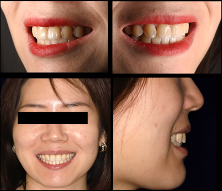
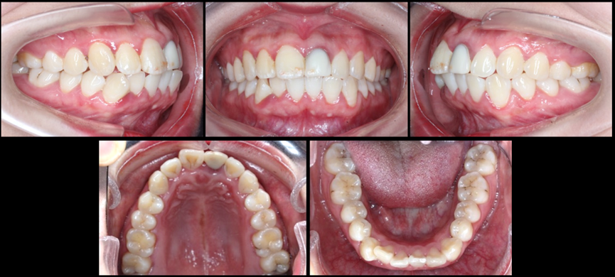
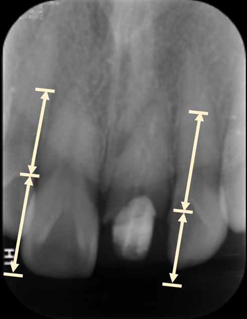
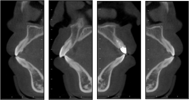
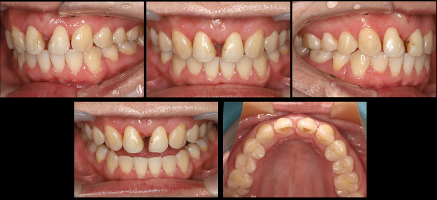
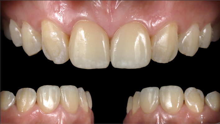
Chief complaint: Requesting improvement of dental aesthetics. Present medical history: The patient underwent orthodontic treatment in an external hospital more than 10 years ago. Nine years ago, due to trauma, the anterior upper teeth were damaged and dental and restorative treatment was performed in an external hospital. Currently, the patient feels that the anterior upper teeth are not aesthetically pleasing and there is protrusion of the mouth, so she visited our department for restoration. Past medical history and systemic medical history: No special conditions. Intraoral examination: Full ceramic crown on tooth 21, with blackish edges and poor tightness. Percussion pain (+/-), no loosening, and swollen gums. Enamel cracks can be seen on the crown of tooth 11. Percussion pain (-), no loosening. Bilateral molar neutral relationship. Anterior teeth overbite. Extraoral examination: The face is basically symmetrical on the left and right. The proportion of the lower one-third of the face is relatively coordinated. The profile is convex, and bimaxillary protrusion is present (Figure 2). Imaging examination: The periapical film of the anterior maxillary area shows that the image of a fiber post can be seen in the middle and upper sections of the root canal of tooth 21. The root filling is underfilled, and a small area of low-density shadow can be seen around the apex. The root is short. No root filling shadow is seen in the root canal of tooth 11. The crown-root ratio is greater than 1:1 (Figure 3). The panoramic tomogram, cephalometric lateral film, and cephalometric analysis results show that the patient has Angle Class I malocclusion, bimaxillary protrusion, and dental crowding (Figures 4 and 5). The cone-beam CT (CBCT) of the anterior tooth area before treatment is shown in Figure 6.



02 Diagnosis and treatment plan
Diagnosis: ① Tooth defect of tooth 21. ② Malocclusion.
Preliminary treatment plan: ① Orthodontic treatment. ② Periodontal treatment. ③ Restorative treatment.
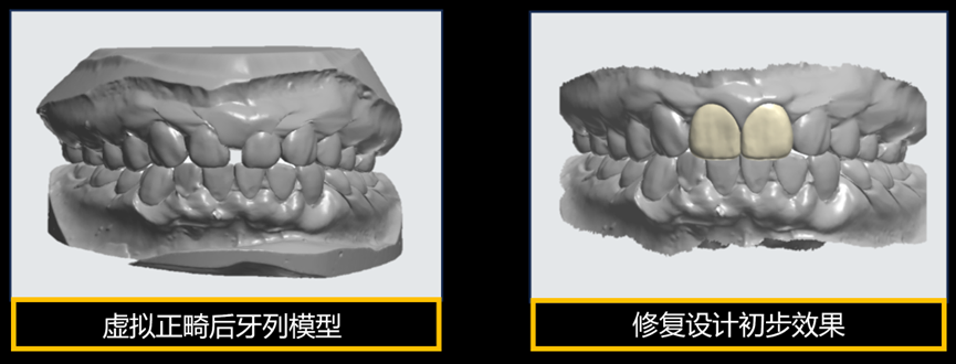
Since this patient needs natural tooth extraction in both the upper and lower jaws simultaneously to provide space, and the roots of teeth 11 and 21 are short. There is a fiber post in the root canal of tooth 21 with a low-density shadow around the apex. Therefore, the orthodontist proposed the following two options: Option one, extract teeth 11, 21, 34, and 44. Use the lateral incisor to replace the central incisor and the canine to replace the lateral incisor in the upper jaw. Option two, conventionally extract teeth 14, 24, 34, and 44. The advantage of option one is that the conditions of the upper central incisors are poor, the orthodontic risk is high. Extraction can reduce the orthodontic risk, and the improvement in profile convexity is more significant. The disadvantage is that aesthetic restoration of multiple anterior teeth has a small tolerance for restoration and high risk. The advantage of option two is that only one anterior tooth is involved in restoration, and the restoration tolerance is large. The disadvantage is that the upper premolars are intact and healthy natural teeth. The orthodontic risk of moving the anterior upper teeth is high, and the improvement in profile convexity is limited. The patient has a high aesthetic demand. From the perspective of preserving more natural teeth, both the restorative dentist and the orthodontist tend to favor the option of extracting central incisors. Therefore, option one is chosen. Before treatment, virtual orthodontic tooth arrangement was performed digitally to predict the long-term restoration effect and assist in formulating the orthodontic treatment plan. Through virtual orthodontic tooth arrangement, it can be found that in order to achieve better anterior tooth aesthetic effects, the patient is highly likely to need periodontal crown lengthening surgery after orthodontic treatment. The three-dimensional model data of virtual orthodontic tooth arrangement is imported into restorative design software for aesthetic analysis and design of the anterior teeth, and the design plan is shown to the patient. The patient is satisfied with the treatment plan and expected effect. Thus, we have determined the treatment plan for this patient:
Treatment plan: ① Periodontal systematic treatment. ② Surgical extraction of teeth 11 and 21 (orthodontic extraction). ③ Orthodontic treatment. ④ Periodontal crown lengthening surgery on teeth 12 and 22. ⑤ Veneer restoration on teeth 12 and 22.
03 Treatment process
Orthodontic treatment stage
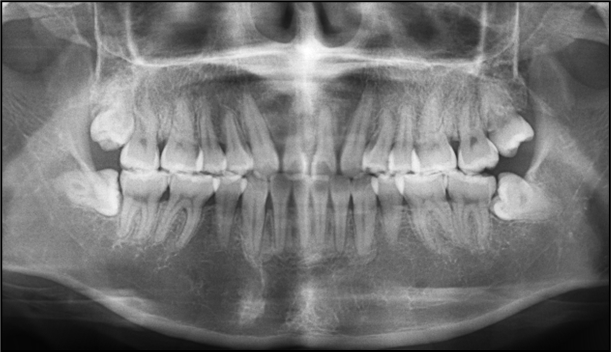
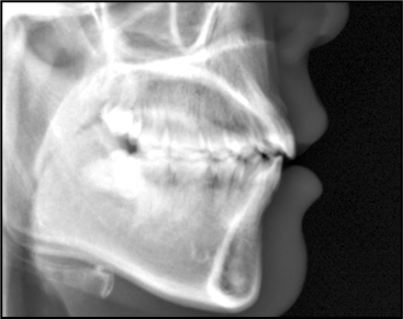
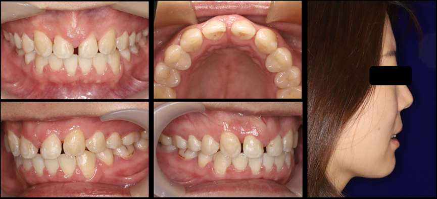
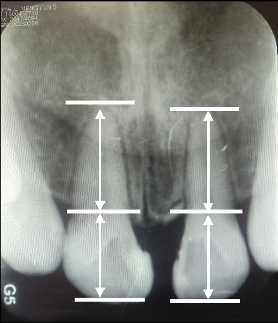
The patient underwent two and a half years of orthodontic treatment. In the later stage of orthodontic treatment, DSD aesthetic analysis was performed guided by restoration to confirm that the reserved space on the left and right of the upper lateral incisors of the patient conforms to the preoperative design. Then, the orthodontic treatment is completed. After orthodontic treatment, the problems of bimaxillary protrusion and dental crowding of the patient have been corrected. The panoramic tomogram, cephalometric lateral film, profile image, and intraoral image after orthodontic treatment are shown in Figures 8-10. The periapical film of the anterior maxillary area shows that the roots of the bilateral upper lateral incisors are relatively short, which indicates that the height of crown lengthening needs to be controlled during periodontal surgery (Figure 11).
Periodontal surgery stage
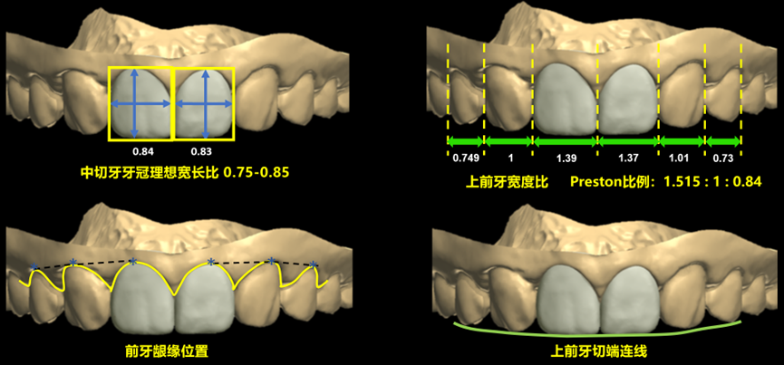
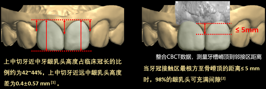
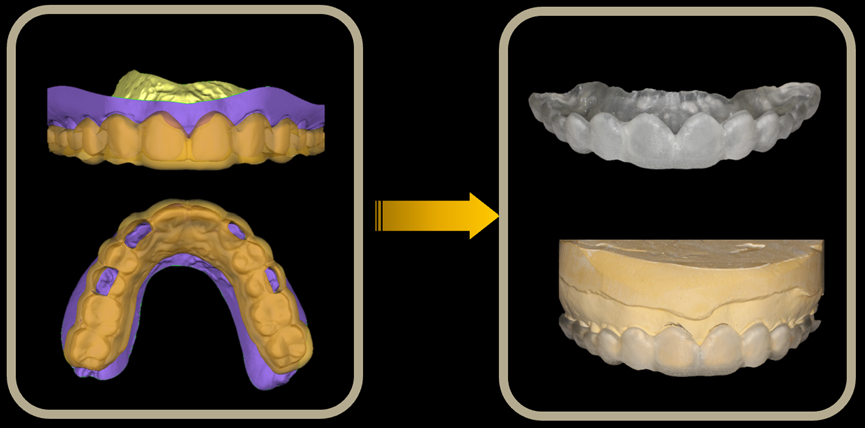
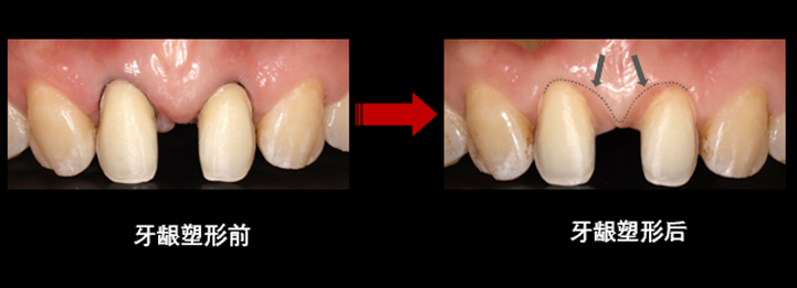
First, the design of the crown lengthening guide plate was performed. The three-dimensional dental data after orthodontic treatment was imported into the 3Shape Dental System oral CAD design software to digitally design the shape of the expected restoration. Then, the design file was imported into the Geomagic Studio software to design the crown lengthening guide plate according to the shape of the restoration. Considering the short root of the upper lateral incisor, the design aims to balance aesthetics and function. During the design process, aesthetic analysis was performed, and the crown shape was designed according to the ideal width-to-length ratio (Figure 12). In addition, we integrated the scanning data and CBCT data and determined the contact area of the central incisor by referring to the position of the alveolar crest. Previous literature has shown that the height of the proximal gingival papilla of the upper central incisor accounts for about 42-44% of the clinical crown length. The height difference between the proximal and distal gingival papillas of the upper central incisor is 0.4 ± 0.57 mm [1]. When the distance from the most apical part of the tooth contact area to the alveolar crest is ≤5 mm, 98% of the gingival papilla can fill the gingival embrasure [2]. During the design process, we ensured the aesthetic ratio of the gingival papilla and ensured that the distance from the alveolar crest to the most apical part of the adjacent contact area is ≤5 mm. The generation of black triangles is avoided through preoperative design (Figure 13). Based on the above analysis and design, we determined the position of gingivectomy. The three-dimensional data of the diagnostic model was imported into three-dimensional reverse engineering software to design and print the crown lengthening guide plate (Figure 14). The periodontal surgeon completed the crown lengthening surgery with the assistance of the crown lengthening guide plate. The intraoral image four weeks after crown lengthening surgery shows that the gums have recovered well (Figure 15).
References: [1] Zhang Hao, Le Di, Hu Wenjie, Cao Zhanqiang, Zhang Yanling, et al. Analysis of the shape characteristics of the gingival curve of 120 healthy young Chinese anterior upper teeth [J]. Journal of Peking University. Health Sciences Edition, 2013(01):58+62-66. [2] Tarnow DP, Magner AW, Fletcher P. The effect of the distance from the contact point to the crest of bone on the presence or absence of the interproximal dental papilla [J]. J Periodontol, 1992, 63(12):995-996.
Temporary restoration stage
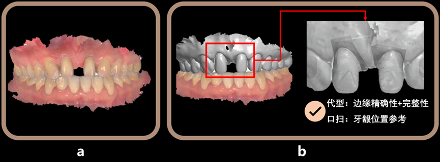
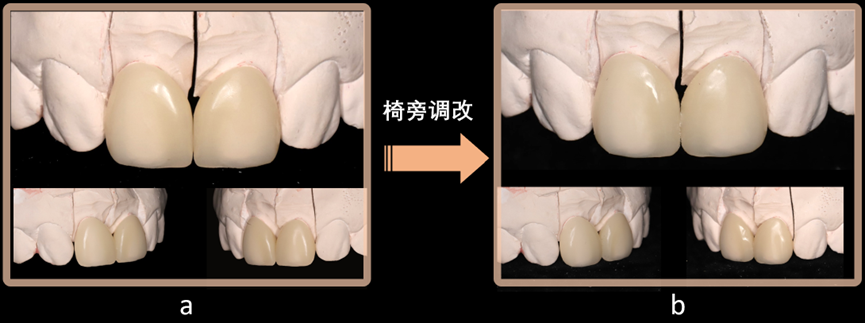
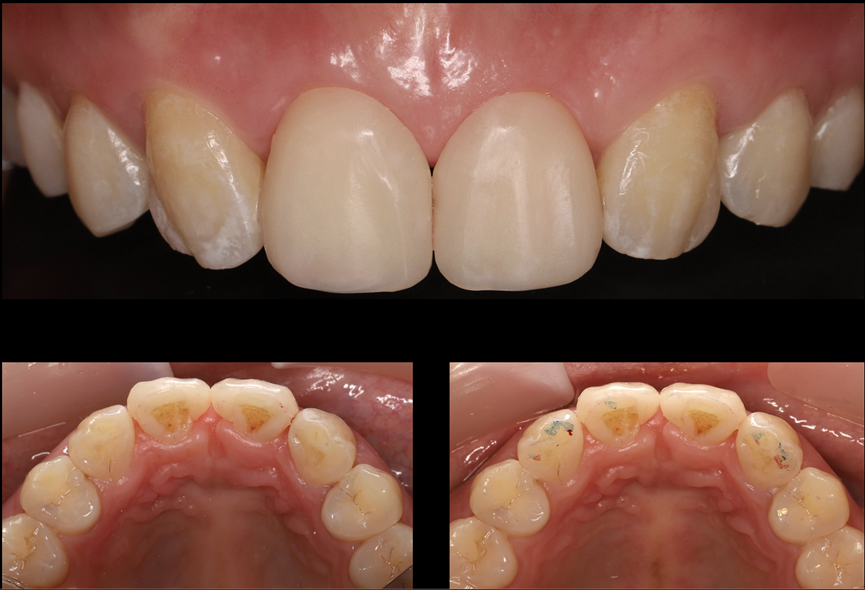
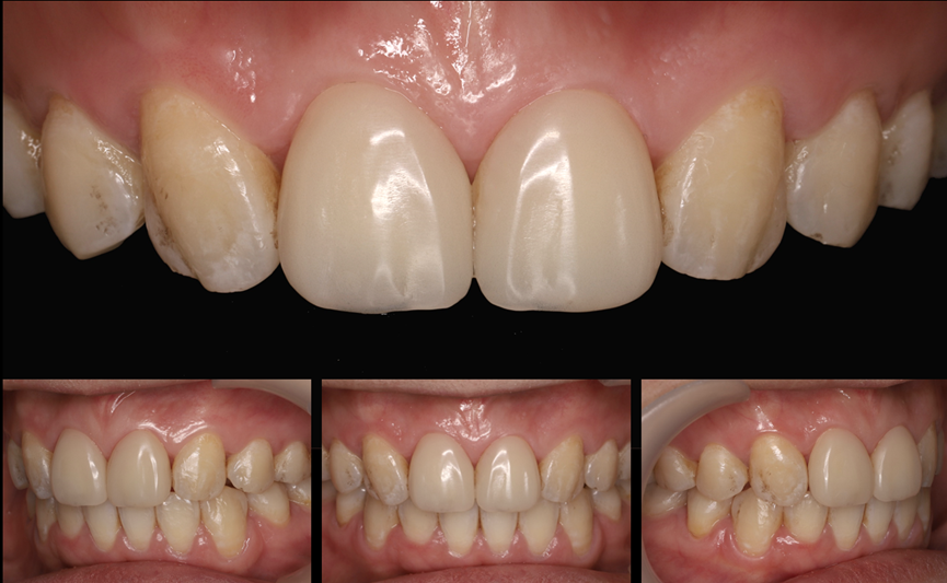
Tooth preparation: After intraoral scanning and taking a silicone rubber impression, the plaster model is segmented and a die is made. The prepared body of the intraoral scan data is registered with the plaster die to obtain a working model combined with intraoral scan + die (Figure 16). The advantage of this operation is that the plaster die can ensure the accuracy and integrity of the prepared body edge, while the intraoral scan data can serve as a reference for the gingival position. Design of veneer shape: During the design process, the CBCT data of the patient after orthodontic treatment is imported. The parts of the two upper lateral incisors are reconstructed and registered on the prepared model. The distance from the alveolar crest to the most apical part of the adjacent contact area is confirmed to be ≤5 mm again, and a polymethyl methacrylate (PMMA) temporary veneer is made (Figure 17). Personalized chairside adjustment of temporary veneer: When fitting the temporary veneer intraorally, according to the patient’s personalized requirements, chairside adjustments were made to the veneer, opening the incisal embrasure and deepening the developmental grooves (Figure 18). The intraoral image of the patient wearing the temporary veneer shows that the edge of the temporary veneer is invisible and tightly fitted. It does not bear the centric occlusion and protrusive and lateral guidance. The occlusion is appropriate. However, there is still some black triangle between the upper lateral incisors at present (Figure 19). The facial image and lip-tooth image of the patient when wearing the temporary veneer are shown in Figure 20. Temporary veneer review: When reviewed two months later, it can be seen that the gingival papilla between the upper lateral incisors fills the gingival embrasure. The gingiva has good color, shape, and texture. The oral hygiene is good. The patient is relatively satisfied with the restoration effect (Figure 21).

Formal restoration stage
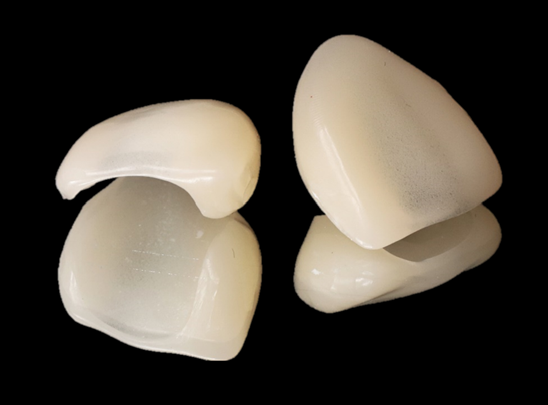
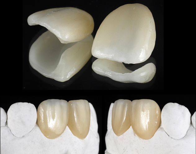
Scan the temporary veneer and copy the shape of the temporary veneer. Using the replication method, the final restoration is made by copying the shape of the temporary veneer. The gingival contour has been shaped, and the gingiva is pink and tough in texture (Figure 22). E.max ceramic material is used for chairside cutting, sintering, glazing, and staining (Figure 23). The clinical bonding of porcelain veneers shows that the gingival papilla fills the gingival embrasure. The gingiva is pink and tough in texture (Figure 24). The facial image and lip-tooth image show that the shape of the restoration is coordinated with the lower one-third of the patient’s face and the overall facial shape (Figure 25). The comparison of the intraoral image and facial image before and after treatment shows that the patient’s profile has changed from convex to straight. The intraoral pink and white aesthetic effect has also been greatly improved.

Follow-up and maintenance stage
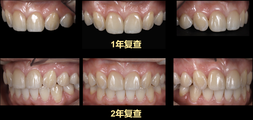
For this patient, mainly periodontal maintenance and occlusal maintenance after orthodontic and restorative treatment are performed. After the patient wears the teeth, a new upper retainer is made and worn all day long. The intraoral images during the one-year and two-year follow-up reviews show that the occlusion of the patient’s anterior upper teeth is stable and the periodontal hygiene is good (Figure 26).
04 Discussion
Digital technology empowering multidisciplinary combined treatment is a method for young dentists to effectively communicate with patients and avoid clinical risks when facing complex cases involving multiple disciplines. Digital technology runs through this case from beginning to end. In orthodontic treatment, through virtual orthodontic tooth arrangement, it assists dentists in confirming the tooth positions for extraction and allows patients to see the preliminary effects of subsequent treatment at the initial stage of diagnosis and treatment through combined orthodontic and restorative design. In periodontal treatment, aesthetic analysis and design are performed by integrating multi-source data through digital technology, and a crown lengthening guide plate is made to assist in determining the gingivectomy height and the position of the contact area of the veneer. In restorative treatment, before making the formal restoration, a temporary resin veneer is cut for the patient. This not only ensures that the gingival papilla can fill the triangular gap and confirms the appropriate position of the adjacent contact area but also meets the patient’s personalized aesthetic requirements. During formal restoration, the shape of the temporary veneer is scanned using the replication method. By taking advantage of the characteristic that the design data can be stored for a long time, the prepared body data is retrieved again to quickly make a formal restoration that is consistent with the temporary veneer, achieving both efficiency and precision.
05 Case review – Professor Liu Yunsong
The highlight of this case is the reasonable use of digital means to assist in formulating the orthodontic extraction plan, predicting the long-term restoration effect, integrating multiple data sources, and designing and making a periodontal crown lengthening guide plate, achieving forward design, good connection among multiple disciplines, and jointly formulating a restoration plan. There are three problems in this case: First, considering the width ratio of the anterior upper teeth in this case, a 3 mm gap is reserved between the bilateral lateral incisors in the orthodontic design to leave space for transforming the upper lateral incisors into central incisors. After the final restoration, the width-to-length ratio is 83%. The reserved gap is slightly larger. From the perspective of periodontal health, the anterior upper teeth should be further retracted to reduce the gap between the two lateral incisors and control the width-to-length ratio after restoration to around 75%. The upper canine teeth can also be appropriately ground to make the shape slightly narrower. This can not only make the canine teeth better simulate the shape of the lateral incisor but also increase the degree of retraction of the anterior upper teeth and reduce the reserved gap, achieving a balance among the width ratio of the anterior upper teeth, the width-to-length ratio of the upper central incisors, and periodontal health. Second, in this case, anterior tooth demineralization occurred during orthodontic treatment, and chalky spots appeared on the incisal one-third of the labial surface. Therefore, during veneer fabrication, chalky spot staining was also performed on the veneer to simulate the appearance of adjacent teeth. If remineralization treatment is performed on adjacent teeth before veneer restoration, better aesthetic effects can be achieved. Third, this case is a patient who undergoes restoration after orthodontic treatment. When reserving space for anterior teeth, the teeth are prone to positional changes. Maintaining the position of the teeth is an important link in anterior tooth restoration.


Leave a Reply