Authors:
Dr. Brian J. Goodacre
Department of Restorative Dentistry, Loma Linda University School of Dentistry, USA
Dr. Charles J. Goodacre
Dean, Loma Linda University School of Dentistry, USA
Prof. Nadim Z. Baba
Department of Restorative Dentistry, Loma Linda University School of Dentistry, USA
This article was originally published in the 7th issue of World Dental Technology in 2020, in the Restoration Techniques section, on pages 37-42.
Abstract:
This article describes how to use intraoral scanners to obtain optical impressions of the edentulous upper and lower arch mucosal surfaces, as well as the denture border areas. It also discusses how to utilize intraoral scanners to record the existing dentures, tooth positions, and abutment data, as well as digitize the centric relation records obtained using a Gothic arch. These scanning data provide all the necessary information for the CAD/CAM fabrication of full arch dentures.
Keywords:
Digital dentistry, intraoral scanners, complete dentures, overdentures, centric relation records
Introduction:
Traditionally, the restoration of complete dentures usually requires five appointments, resulting in a longer treatment time and higher costs. Some dentists have reduced the number of appointments by combining individual steps. With the introduction of CAD/CAM technology for the fabrication of complete dentures, the number of appointments can be reduced to as few as two, significantly shortening the treatment time. However, the method of obtaining impressions for complete dentures remains unchanged. Intraoral scanners have been used for decades in patients with dentition, and more recently, they have also been successfully applied in the fabrication of removable partial denture frameworks with good retentive and stability characteristics. However, there are still challenges in scanning edentulous arches. In studies investigating the acquisition of edentulous arch data using intraoral scanners, it was found that some scanners and software lack the capability to achieve accurate digital scans. Therefore, in other studies, auxiliary tools such as pressure indicators and composite marker materials have been tested to improve the scanning of the edentulous palatal region using intraoral scanners. The conclusion was that these auxiliary tools can improve the quality of optical impressions. It is important to also study the accuracy of intraoral scanner records of the edentulous arches’ soft tissue morphology and denture border areas. Thus, the purpose of this article is to describe how to obtain all the anatomical and occlusal information, as well as the records of centric relation, using intraoral scanners to fabricate a full arch denture and an implant-supported overdenture.
Case Presentation:
A 78-year-old male patient presented with a desire to replace his dentures and requested that the new dentures accurately replicate the appearance of his existing dentures. As he wished to retain the existing dentures for occasional use as a backup, he wanted to minimize any noticeable differences between the new and old dentures. Previously, the patient (at the second author’s practice) had received full arch denture restoration treatment. Subsequently, the mandibular complete denture was replaced with an implant-supported overdenture. Over the years, the transition area between the porcelain teeth and the denture base had become discolored, and one of the maxillary lateral incisors had become loose and had been repaired (Figure 1).

As mentioned earlier, the patient desired to replicate the irregularities of the old dentures, especially in the anterior mandibular teeth, as these irregularities provided a natural appearance to the dentures (Figure 2). The vertical dimension of occlusion had been established, and no changes were required in this case. After a comprehensive discussion of the treatment plan, the patient decided to proceed with a full arch denture for the maxilla and an implant-supported overdenture for the mandible.

Procedure:
During the first appointment, an intraoral examination was performed, and the extension of the maxillary denture flange in the posterior midline was marked with a colored marker on the edentulous ridge (Dr. Thompson’s Color Transfer Applicators, USA) (Figure 3). Digital impressions were taken using an intraoral scanner (TRIOS 3, 3Shape, Denmark) for both the maxilla and mandible. The patient’s lips and cheeks were gently retracted with the thumb and index finger to roughly determine the denture border areas and the position of attachment to the labial/buccal frenum (Figure 4).


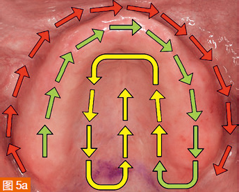
Carefully retract the soft tissues back to the position corresponding to the extension of the denture borders without overstretching. The scan path for the edentulous maxilla starts from the edentulous ridge, then scans the entire palate, and finally covers the labial/buccal areas (Figure 5a). The mandible is first scanned in the edentulous ridge area, then the labial/buccal areas, and finally the lingual extension area of the denture border (Figure 5b). It is important to complete the labial/buccal scan in one step. Returning to missed areas afterwards can result in errors in the digital impression due to the soft tissues retracting to different positions.


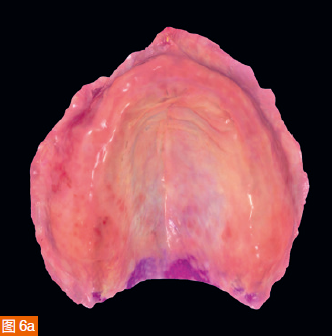
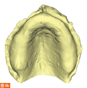
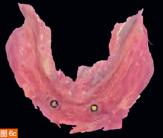
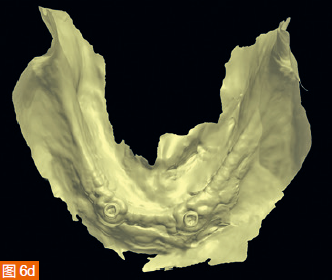
The intraoral digital impressions of the maxilla and mandible are displayed in color and monochrome in Figures 6a to 6d, respectively. The centric relation record is obtained using an arrow angle recorder, also known as a Gothic arch tracing device (AMD AvaDent, Global Dental Science, Netherlands) (Figure 7). The same intraoral scanner is used to scan this centric relation record (Figure 8). Additionally, the existing dentures are scanned using the intraoral scanner to obtain digital data of the tooth positions and denture base shape for designing and fabricating the new CAD/CAM restorations. The intraoral digital impressions of the maxilla and mandible, digitized centric relation records, and scanned data of the existing dentures are saved in the STL (Standard Tessellation Language) format and sent to Global Dental Science as documentation for the fabrication of the maxillary and mandibular dentures.


The digitized Gothic arch record serves as the centric relation record, allowing the virtual mounting of the optical impressions of the maxilla and mandible in centric relation and at the established vertical dimension of occlusion (Figure 9). Based on the scan of the existing dentures, new dentures are created within the software to replicate the tooth positions of the old dentures (Figure 10). A CAD/CAM aesthetic try-in denture (BTI AvaDent, Global Dental Science) is fabricated to check the fit, occlusion, and aesthetics of the dentures (Figure 11).


During the second appointment, the fit, occlusion, and aesthetics of the try-in denture are evaluated, and only slight adjustments to the height of the maxillary incisal edges are needed (Figure 12). Then, the aesthetic try-in denture for the maxilla is scanned, and the scan data is transmitted to Global Dental Science, where the dentures are milled using a single-layer material to complete the fabrication of the maxillary complete denture and the mandibular implant-supported overdenture.


During the third appointment, the final dentures are delivered to the patient. After checking with pressure-indicating paste, only minimal adjustments are made to the tissue surfaces of the two final dentures. The dentures are then placed on the frameworks and slightly adjusted. Two Locator attachments (Zest Anchors, Zest Dental Solutions, USA) are picked up on the mandibular overdenture using the Pick-up technique. The patient is very satisfied with the fit, stability, and aesthetics of the new dentures (Figure 14).

Discussion:
The use of intraoral scanners allows for the capture of soft tissue morphology in edentulous arch patients, including the entire denture border areas, and facilitates CAD/CAM fabrication of complete dentures using the acquired digital data. This technology offers several advantages. It reduces the number of treatment appointments as individual trays and traditional impression materials are no longer required, and there is no need to send or mail impressions or bite records to the dental laboratory, thereby shortening the overall treatment time from start to delivery of the final dentures. In the presented case, the entire treatment was completed in three relatively short appointments, with an interim aesthetic try-in during the second appointment. If the aesthetics of the existing dentures are acceptable, they can be scanned and used as a template for tooth positions in the new dentures. In this case, minimal adjustments were made during the second appointment try-in, demonstrating that this digital workflow can result in the delivery of final dentures after only two appointments. However, in this specific case, there were three appointments due to the additional try-in appointment conducted to assess the fit, occlusion, and aesthetics of the dentures. Scanning the edentulous arches and digitizing the impressions not only saves time but also eliminates the discomfort and waiting time associated with conventional impression materials setting in the patient’s mouth. In this case, scanning the maxilla took 2 minutes, and scanning the mandible took 5 minutes. The scanning time can be further reduced with more experience and improvements in the scanner technology.
However, scanning the mandible is more challenging than scanning the maxilla and may even be impossible for some patients. In a previous case with the author, only partial regions of the vestibular border, alveolar ridge, and lingual extension of the denture could be scanned. Then, a test denture (AvaDent WTI, Global Dental Science) was milled based on the incomplete scan results, and conventional functional impressions were taken to determine the missing lingual border of the denture. It should be noted that an easy method to achieve a lingual extension border was to gently retract the soft tissues with the fingers, allowing for a clear display of the attachment areas of the rugae and frena, which has been proven to be successful and produces an acceptable closed denture border. It would be helpful to observe the differences in border extension between different dentists using their respective conventional techniques for the same patient to verify the deviations. The author believes that gently retracting the mucosa with the fingers and scanning the stretched soft tissues can create a valve-like border seal in all directions. However, it should be noted that not all patients are suitable for successful intraoral scanning. Selected patients should have sufficient alveolar ridge height and attached mucosa to allow control of the soft tissues.
When scanning the lingual side of the mandible, a challenging area to determine the denture border extension is in the retromylohyoid region and the posterior area behind the retromylohyoid groove. A technique similar to the one proposed by Neil in 1932 to measure the shallow fossa shape in the retromylohyoid region could be used to determine the depth required for the lingual border of the denture.
Another challenge in the CAD/CAM fabrication of complete dentures is establishing bilateral balance. The intraoral digital impressions of the edentulous arches are still in the early stages, and there is currently no comparison study on the accuracy between intraoral scan impressions and traditional functional impressions. Additionally, as only one brand of intraoral scanner was used in this case report, further testing is required on other intraoral scanners. Finally, manufacturers need to enhance their development capabilities in scanning technology to capture soft tissue data in edentulous arches more effectively.
Conclusion:
This article described a case of complete denture restoration in which intraoral scanners were used to obtain digital impressions. It was determined through this case that after capturing digital impressions using intraoral scanners, successful fabrication of a complete denture for the maxilla and an implant-supported overdenture for the mandible can be achieved. An advantage of intraoral scanning is the ability to generate a true static mucosal impression, resulting in good mucosal adaptation and sufficient stability for the CAD/CAM milled dentures. Furthermore, intraoral scanners enable the digitization of traditional centric relation records and existing dentures in the patient’s mouth. By providing a fully digital template, the tooth positions and denture base positions of the old dentures can be replicated as desired by the patient in the new dentures. The method presented here simplifies the clinical process and eliminates the need to send traditional impressions and bite records to the dental laboratory.
Author Biographies:

Division of Prosthodontics, Loma Linda University School of Dentistry, USA


Division of Prosthodontics, School of Dentistry, Loma Linda University, USA


Leave a Reply