
Author: Dr. Manfred Nilius (Germany)
In the field of dental implantology, although complications during surgical procedures are not common, they can still occur. Therefore, knowledge of possible complications and effective strategies to deal with them are an indispensable part of dental implant practice. The basis for minimizing errors and successfully implanting implants is a predictive treatment plan and the ability to quickly identify unexpected situations during surgical procedures and adjust the treatment strategy in a timely manner. Imaging information and three-dimensional digital treatment planning are effective tools that enable dental surgeons to better control the predictability of intraoral treatment processes and improve postoperative treatment outcomes. Especially for cases of immediate implant placement and immediate restoration after tooth extraction, sufficient primary stability has an important impact on the long-term success rate of the implant. This article discusses a case of immediate implant placement in the maxillary anterior region with high aesthetic requirements and the complications that occurred during the operation. The article particularly emphasizes the advantages of a fully digital workflow without the need for traditional impression taking and the management of intraoperative complications.
Keywords: complications, primary stability, immediate implant placement, immediate restoration
Patient Examination Results
A 35-year-old female patient visited our clinic for treatment due to a crown fracture of the right maxillary central incisor #11. About six years ago, due to anterior tooth trauma, the #11 tooth underwent root canal treatment. After the treatment, no post was used, and a metal-ceramic crown was placed for restoration. The crown fracture was caused by extensive cervical caries. On the X-ray film, a cloud-like radiopaque shadow could be seen in the apical region, which was due to overfilling of the root canal filling paste (Figure 1). As an additional finding, in the digital tomosynthesis (CBCT), a white radiolucent line was found in the apical region of the #22 tooth that had undergone root canal treatment, suspected to be an apical cyst (Figure 2). When examining the #11 and #22 teeth, the patient had no clinical symptoms and signs. The patient was five months pregnant, did not smoke, and had no chronic medical history.

Figure 1: Preoperative X-ray examination of tooth #11: The large defect at the tooth neck and the overfilled root canal filler in the apical part are clearly visible.

Figure 2: Digital panoramic tomogram, with an additional finding of whitening in the apical region of tooth #22.
The patient had a natural dentition with restorations in the mouth. The plaque index (API) was less than 25.0%, the oral hygiene index (OHI) was 1, and there was no bleeding index (BOP). The oral hygiene condition was very good.
Treatment Planning
After consultation with the patient and a detailed explanation of the available treatment options, although the adjacent teeth had crown restorations, we decided to abandon the conventional fixed restoration and adopt implant restoration treatment. The thick gingival biotype, bone density of 550 to 650 Hounsfield units (HU), and good bone quality (classified as D2 according to Lekholm and Zarb) allowed for immediate implant placement and immediate restoration. According to the results of a recent systematic literature review, immediate implant placement can maintain the alveolar ridge volume and is suitable for the restoration of the maxillary anterior region with high aesthetic requirements. The survival rate of implants after immediate implant placement does not seem to be significantly different from that of conventional implant placement in the healed jawbone. However, the statements about the effects of immediate implant placement in the literature are not consistent. It has been reported that, among other factors, compared with implant placement in the healed jawbone, complications occur more frequently and the failure rate is higher after immediate implant placement. Moreover, the view that immediate implant placement can maintain the alveolar ridge volume by blocking the physiological remodeling of the alveolar ridge after tooth extraction has not been fully supported by the literature. The clinical research results on immediate or delayed loading of implants are also inconsistent. Some studies believe that the current research status is not sufficient to clarify the advantages and disadvantages of the two loading schemes. Other studies show that there is no significant difference in the aesthetic and functional effects of the two loading schemes. In view of the current unclear evidence, it is necessary to carefully select cases suitable for immediate implant placement and immediate loading and formulate a suitable surgical plan accordingly to obtain predictable treatment results.
In the clinical situation of this patient, according to the three-dimensional treatment plan, it was planned to extract the loose root fragments and then fabricate a surgical guide for the implantation of the implant under full guidance. The asymptomatic root fragments were retained in the alveolar socket during the preoperative preparation stage to maintain the alveolar ridge volume. During the same operation, it was also planned to perform an apical resection of the #22 tooth if necessary.
A temporary crown was selected for immediate implant restoration to shape the soft tissue and form a good emergence profile of the restoration. Before performing the surgical operation on the patient, the working model was mounted on a phantom head to practice the surgical procedure. The purposes of the practice were as follows:
1. To test the surgical procedure on the model.
2. To familiarize with the operation of the surgical guide (check the seating and stability of the three-dimensional surgical guide) and accessories such as sleeves in the mouth.
3. To determine the implantation depth of the implant.
4. To verify the operability of the treatment plan from virtual design to the actual patient situation.
5. Using the demonstration model to make the treatment process transparent to the patient can help the patient understand the treatment plan more intuitively and improve the effectiveness of informed consent.
Diagnosis and Model Surgery
First, imaging diagnosis was completed using CBCT. An intraoral scan was performed using the 3Shape TRIOS scanner (Figure 3). The position and size of the implant were planned using the 3Shape implant software (Figure 4).

Figure 3: Intraoral scan of the maxilla.

Figure 4: Virtual design of the implant position using 3Shape software.
Selecting an ideal implant suitable for the patient’s clinical situation is crucial. The same is true for this case of immediate implant placement after tooth extraction. SICace®, SICmax®, and SICtapered® are three types of implants with an internal hexagonal connection, different lengths and diameters, and different external designs and indications.
According to the manufacturer’s product description, the SICace® implant is suitable for bone quality and implant indications and is especially recommended for implant treatment combined with bone augmentation. The SICmax® implant is suitable for D2 to D4 bone quality.
Initially, a tapered SICtapered® implant with a diameter of 4.2 mm and a length of 13.0 mm was selected according to the patient’s clinical situation. The SICtapered® tapered implant is suitable for different bone qualities. The surgeon can flexibly perform step-by-step drilling according to the bone density to control the implant to achieve ideal primary stability. The DICOM data analysis of the residual root anatomy and the periapical bone volume showed that it was necessary to make full use of the periapical bone tissue to obtain sufficient primary stability. The SICtapered® tapered implant has a conical shape and high-cutting-efficiency implant threads, so a stepped preparation should be selected to exert a slight bone compression effect when the implant is inserted. Another advantage of this case is that the alveolar ridge crest bone is thick, which ensures better stability at the alveolar ridge crest after tooth extraction.
After matching the DICOM data with the digital impression data, a model and a surgical guide were fabricated by 3D printing in the dental laboratory (Jörg Pohl Dental Laboratory, Germany) (Figure 5). The model was made of photosensitive plastic by 3D printing. The surgical guide was also made of a biocompatible Class 1 synthetic resin that can withstand high temperature and high pressure sterilization by 3D printing. The drilling sleeve was reinforced with a metal sleeve to ensure good guidance of the implant drill. The surgical guide was retained by the adjacent teeth. The side monitoring window ensured that the position of the guide could be continuously monitored to be correct and stable during the implantation process (Figure 6).

Figure 5: 3D printed surgical guide and model.

Figure 6: Side monitoring window for checking the correct seating of the surgical guide.
According to the standard drilling operation procedures provided by the implant manufacturer (Figure 7a and b), the implant bed preparation and implant placement under full guidance were performed on the model. After completing the model practice operation according to the procedure, a scan body was connected to the implanted implant, and an optical impression was taken using a digital scanner. Based on the scan data, a model was fabricated by 3D printing, and the suprastructure was fabricated on the implant die corresponding to the used implant in the dental laboratory (Figure 8). A long-term temporary crown made of polymethyl methacrylate (PMMA) and fixed with screws was designed and fabricated using 3Shape dental design software (Figure 9).
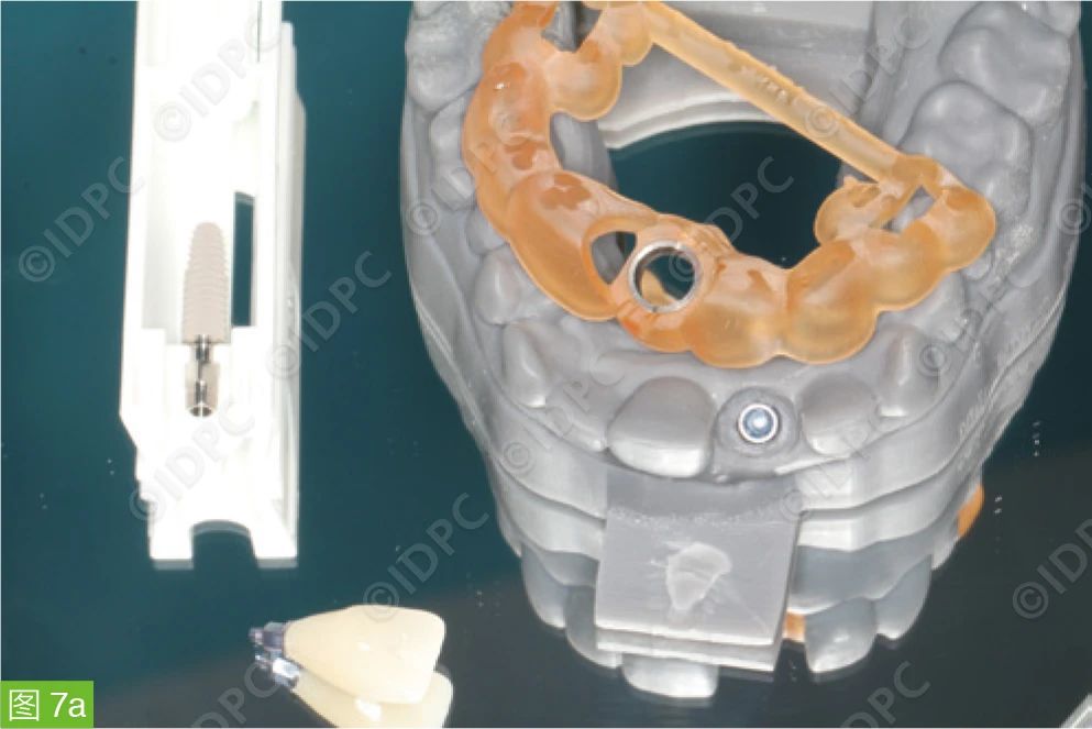

Figure 7a and b: Preoperative model surgery.

Figure 8: Implant die (blue) for fabricating the suprastructure.

Figure 9: Fabrication of an implant-supported single crown fixed with screws on the model.
Surgical Procedure and Immediate Restoration
The root was retained in the alveolar socket until before the implantation, maintaining the alveolar ridge width. The buccolingual width of the alveolar ridge was about 9.1 mm, providing a good starting point for implant restoration (Figure 10). Due to the long operation time, in addition to local anesthesia with UDS forte, midazolam and propofol were used for analgesia. First, an apical resection (WSR) was performed on the #22 tooth.

Figure 10: Good clinical condition of the alveolar ridge before the operation.
An incision was made at the alveolar ridge crest of the edentulous area and the buccal/palatal gingival sulcus of the #12 and #21 teeth to expose the residual root. The mucoperiosteal flap was fully elevated without making a vertical releasing incision to clearly expose the surgical area. The remaining #11 tooth root was loosened with a fine bone file and removed without damaging the buccal bone plate (Figure 11). At the same time, an incision was made in the apical region of the affected tooth to expose the overfilled position of the root canal filling material in the apical region, remove the overfilled material that was extruded under the periosteum, and observe the position and direction of the implant at the root side during the implantation process from this view (Figure 12). The implant bed was prepared according to the standard drilling protocol provided by the manufacturer (Figure 13). The implant bed preparation was only carried out in the apical region of the alveolar socket. When implanting the SICtapered® tapered implant, it was found that the insertion torque was only 25 Ncm, and sufficient primary stability required for immediate loading could not be obtained (Figure 14). The increased mobility of the implant could be observed with the naked eye. Therefore, we decided to remove the implanted implant. There is no unified understanding in the literature about the minimum torque for immediate loading. However, it is generally considered that an insertion torque of more than 30 Ncm is acceptable for immediate implant placement to achieve primary stability.

Figure 11: Minimally invasive extraction of the #11 residual root after the mucoperiosteal flap was elevated.

Figure 12: An additional incision in the apical region to remove the root canal filling material and monitor the position of the implant at the root side.

Figure 13: Preparation of the implant bed for the SICtapered® tapered implant.

Figure 14: The SICtapered® tapered implant did not have sufficient primary stability and had visible mobility, so it was necessary to remove it immediately.
A thicker and longer SICmax® implant (4.7 x 14.5 mm) was used, and the primary stability requirement could be achieved with an insertion torque of 35 Ncm (Figure 15). The root portion of the SICmax® implant is cylindrical, and the crown portion is similar in shape to the SICtapered® tapered implant but has an additional microthread structure compared with SICtapered®. Therefore, it can be fixed in the alveolar socket below the alveolar ridge crest and form stable two-point contacts with the alveolar bone at the root and crown sides.

Figure 15: Implantation of the SICmax® implant with a size of 4.7 x 14.5 mm.
The postoperative X-ray film showed that the bone walls around the implant in the extraction socket were intact (Figure 16). After the successful implantation of the implant, we first tried on the screw-retained temporary restoration to confirm its proper seating (Figure 17). Then, the retaining screw was used to close the internal connection part of the implant, and granular allogeneic bone substitute material was filled into the gap between the implant surface and the inner wall of the alveolar socket to prevent the particles of the substitute material from entering the screw channel (Figure 18). It is recommended to fill the gap around the implant because compared with the method of not filling the gap, this can obviously better preserve the alveolar ridge morphology. The bone defect at the buccal window of the apex was also filled with bone substitute material to maintain and support the contour of the labial alveolar process. In the alveolar ridge crest area, platelet-rich growth factor PRGF was introduced through the gingival surface of the temporary crown to cover the granular bone substitute material as the final closure of the wound (Figure 19). Then, the screw was tightened with a torque ratchet. The screw channel of the temporary crown was sealed with resin. Then, the implant crown was bonded and fixed to the adjacent areas of the #12 and #21 teeth with resin. The soft tissue was treated by pressing the flap from the palatal side to the labial side to shape the labial gingiva and interdental papilla. A 5 x 0 PTFE suture was used, and a double-cross suture method (double-cross vertical mattress suture) was used to suspend and coronally fix the soft tissue (Figure 20a and b). Postoperatively, the patient was treated with ibuprofen 600 mg and Isocillin 1.2 Mega 1.1.1 for three days. The follow-up examination one week after the operation showed that there was no dehiscence or infection in the surgical area soft tissue (Figure 21). The patient had no complaints of discomfort. Three months after the operation, the final crown was placed. The soft tissue around the implant showed no signs of inflammation, and the gingival morphology was harmonious with the adjacent teeth (Figure 22).

Figure 16: Postoperative X-ray examination after the implantation of the SICmax® implant.

Figure 17: Try-on of the screw-retained long-term temporary crown.

Figure 18: Filling of the gap around the implant with bone substitute material.

Figure 19: Application of PRGF on the tissue contact surface of the implant crown before placement to cover and stabilize the bone substitute material.
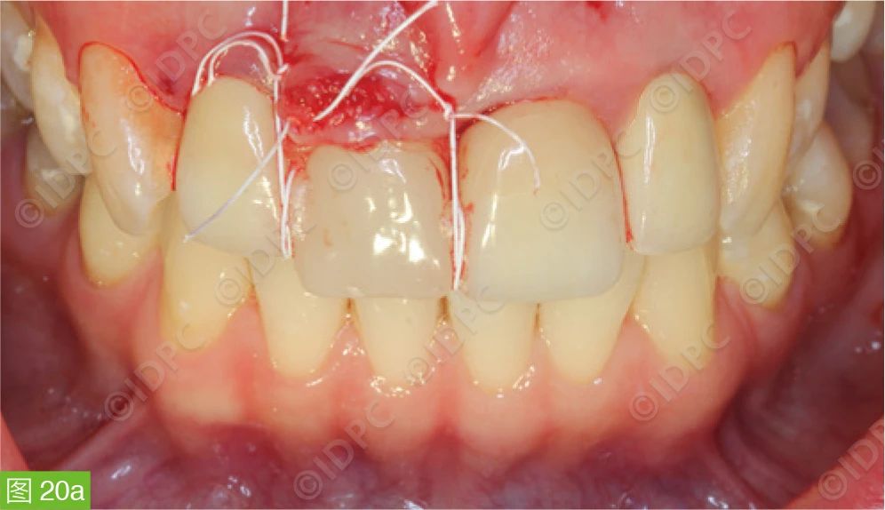
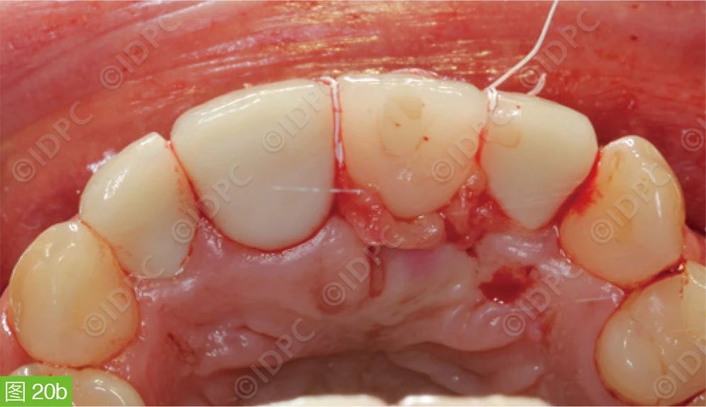
Figure 20a and b: The implant crown was bonded to the adjacent areas of the #12 and #21 teeth with composite resin material and stabilized by pressing the flap and double-cross vertical mattress suture to shape the soft tissue at the root side of the adjacent area.

Figure 21: Condition one week after the operation.

Figure 22: Three months after the operation, the situation of the final porcelain restoration placement.
All figures are sourced from © Dr. Manfred Nilius

Conclusion and Outlook
This case shows that even if complications occur during the operation, through appropriate measures to manage the complications, it is possible to obtain good clinical results and sufficient primary stability and achieve immediate loading of the implant. Although this complication management experience has been confirmed in our current practice, the final clinical outcome of this patient still needs to be evaluated through long-term follow-up. In terms of the workflow, in the future, dental practitioners may submit 3D data such as intraoral scans and CTs, professional service providers will provide 3D data integration and plan design, and dental doctors will conduct professional supervision and final approval. In this way, in clinical practice, dental surgeons can fully focus on clinically relevant surgeries and treatments, benefiting patients.


Leave a Reply