
Author: Ju Rui
West China Hospital of Stomatology, Sichuan University
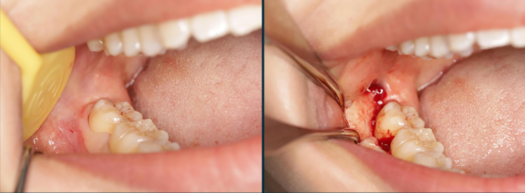
The impacted mandibular third molars are relatively common in clinical practice. Usually, the affected teeth are extracted by removing the bone and creating a window on the buccal side of the third molar. After the operation, patients are prone to experience discomfort symptoms such as the destruction of the shape of the retromolar pad, the accumulation of food residues, the loosening of the second molar, and tooth sensitivity caused by the exposure of the distal cervical area of the tooth. In the past, some surgeons used the bone cap technique to preserve the buccal cortical bone of the third molar, but usually there were situations such as the difficulty in retaining the bone cap or the excessively large wound caused by designing the retention form. Therefore, this article aims to explore a minimally invasive tooth extraction method using the bone cap technique without expanding the original incision design. The core of the bone cap technique lies in preserving the buccal cortical bone of the third molar to reduce the bone window. This method not only reduces the surgical trauma but also helps the rapid recovery of the patient’s wound after the operation.
Case 1: Rectangular Bone Cap
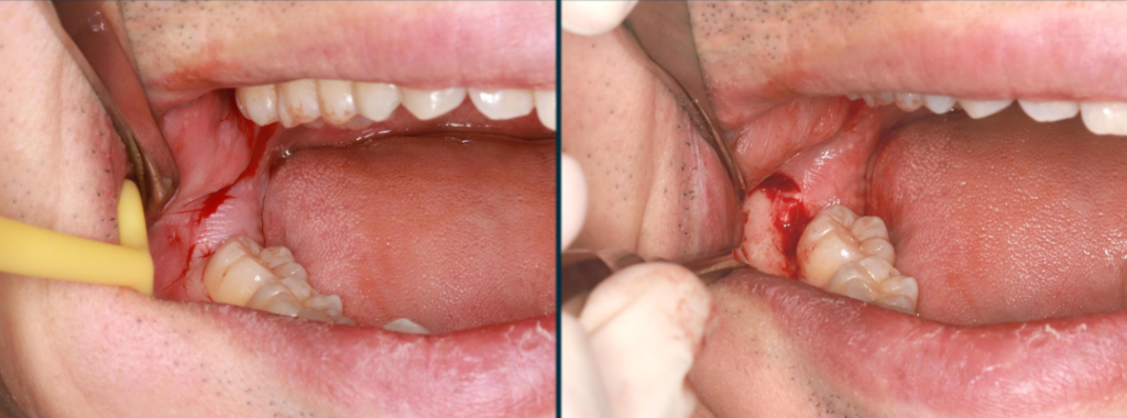
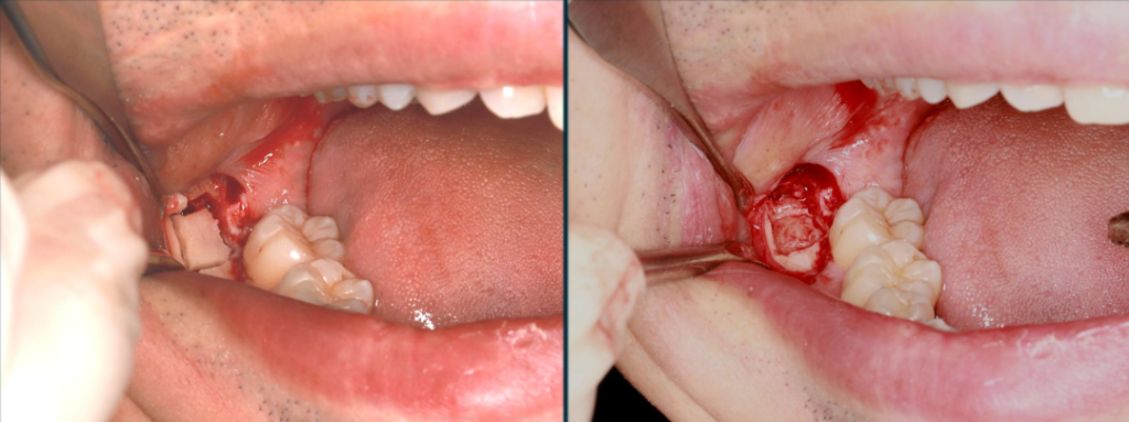
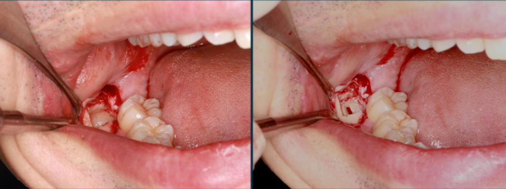
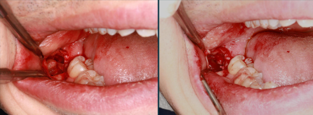
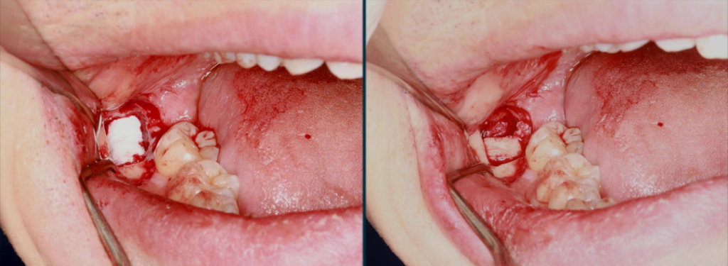
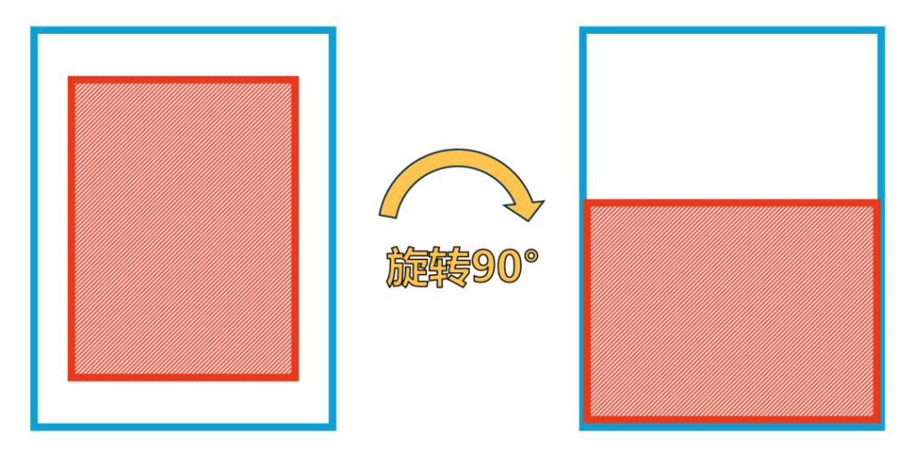
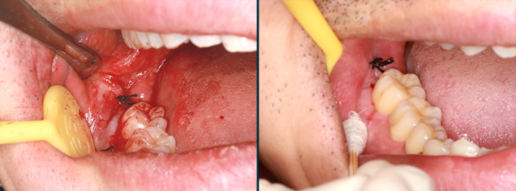
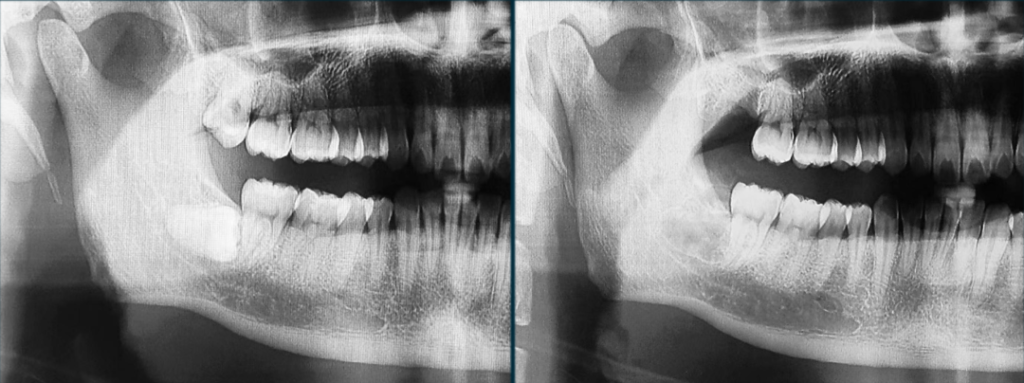
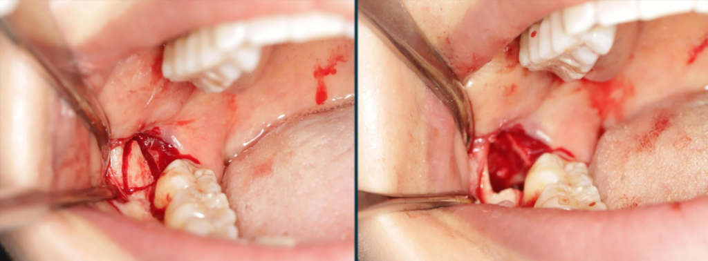
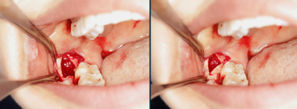
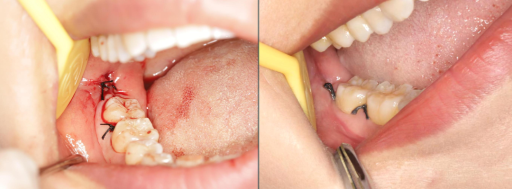
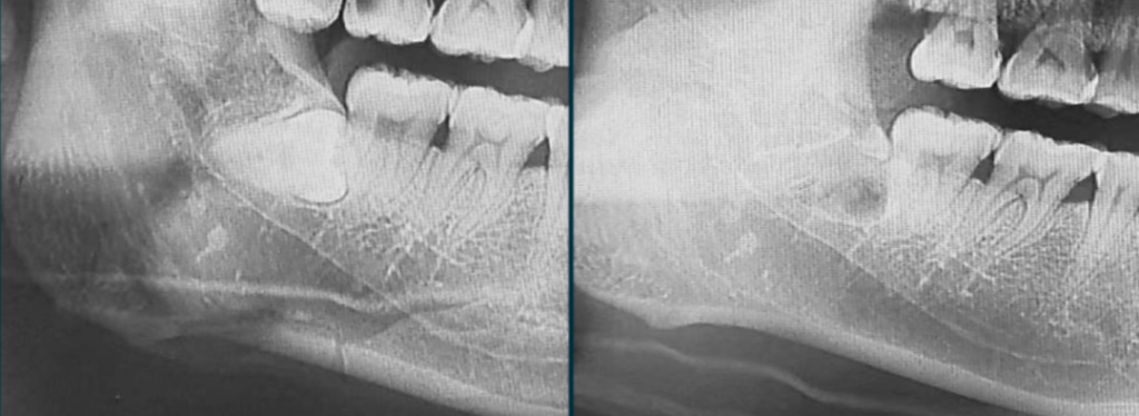
This article mainly introduces two cases in detail to demonstrate the specific application of the bone cap technique. In the first case, we adopted the rectangular bone cap design. During the operation, first, an angulated flap was raised to expose the bone surface of the surgical area. Then, a rectangular bone window was carved to expose the crown of the tooth. Next, the resistance of the crown was removed by “T”-shaped crown sectioning. After elevating the crown, the extraction socket was cleaned, curetted, and irrigated. Finally, a hemostatic material was packed, and the rectangular bone cap was rotated into place, and the wound was sutured. One week later, the stitches were removed for reexamination, and the comparison of panoramic radiographs before and after the operation showed a good treatment effect.
Case 2: Triangular Bone Cap
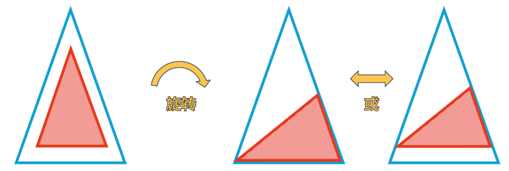
In the second case, we improved the design of the bone cap and adopted the triangular bone cap. This design makes it easier for the bone cap to be seated in the bone window, and it can be easily seated by moving the bone cap back and forth in the bone window. Similarly, the comparison of panoramic radiographs before and after the operation showed a good healing effect.
Summary and Discussion
The minimally invasive bone cap design preserves the cortical bone of the surgical area as much as possible without expanding the scope of the traditional incision, achieving the effects of preventing the collapse of the gingival flap, promoting the formation of soft tissue, and preventing the loosening and sensitivity of the second molar. The rectangular design adopted in Case 1 has a relatively high operational difficulty. If the difference between the long axis of the bone cap and the short axis of the bone window is too large, the bone cap may not be seated properly or the clasping force may be insufficient. Therefore, in Case 2, it was improved to the triangular bone cap design, which can be easily seated by moving the bone cap back and forth in the bone window.
Most of the structure of the minimally invasive bone cap is cortical bone, which will be slowly absorbed during future osteogenesis. However, this design provides conditions for guiding and promoting the formation of the distal soft tissue of the second molar. Therefore, the treatment effect can be achieved 1 to 2 weeks after tooth extraction.
Author’s Profile
Ju Rui, Attending Physician

Ju Rui, an attending physician in the West China Hospital of Stomatology, Sichuan University, holds a doctoral degree. He has been engaged in the clinical diagnosis and treatment of oral and maxillofacial surgery for a long time and is proficient in various alveolar surgical procedures, especially in the extraction of various difficult impacted teeth.


Leave a Reply